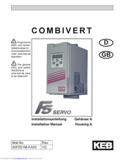
This instruction manual describes the COMBIVERT F5 ELEVATOR DRIVE. Before working with the unit the user must become familiar with it. This especially applies to the knowledge and observance of the following safety and warning indications. The icons used in this instruction manual have the following meaning: c Danger Pay Attention Information. The digital servo controller KEB COMBIVERT F5-SERVO serves exclusively for the control and regulation of permanent magnet AC servo motors. Using a motor data table in this instruction manual, the F5 - SERVO control can be quickly adjusted and commissioned for anyone of the KEB type SM servo motors. With a few additional adjustments, the.
Issue 06/2005 KEB COMBIVERT F5-BASIC / COMPACT / GENERAL 3.2 Part.No.: 00.F5.GEA-K320 APPLICATION MANUAL Charge 40,- Euro. View and Download KEB COMBIVERT F5 instruction manual online. 1.5.4.0kW 230 V 1.5.7.5kW 400 V. COMBIVERT F5 dc drives pdf manual download. Also for: Combivert f6. This manual do not lay claim on completeness. The pictograms used in this manual mean: Danger Warning Caution Attention observe at all costs Information Help Tip 1.2 Product description This instruction manual describes the frequency inverter series KEB COMBIVERT F5 for lift drives.
The F5 COMBIVERT drive is designed to handle the most difficult applications worldwide and is available up to 1,200 Hp. The F5 platform is extremely flexible and offers configurable safety options, heatsinks, encoder interfaces, and communication ports.
- Keb Combivert F5 Manual This could mean a short in the motor, motor leads, connections or inside of the inverter. Permissible inverteg cross-sections and tightening torques of the terminals permissible cross-section flexible with wire-end Max. User Manual Pdf Download.
- This manual describes the KEB COMBIVERT F5. Particular attention is paid to the installation, the connection as well as the basic operation. Due to the various application and programming possibilities, the application-specific connection and/or wiring diagram, the parameter adjustment.
Product Details
Tech Specs
Related
Product Details
The COMBIVERT F5 control card is available in three different performance/feature levels to match application requirements: Basic, Compact, and Application
Available in 230, 480 and 690 VAC classes through 1,200 Hp.
Modular communication operator concept for ultimate flexibility – Supports: EtherNet/IP, ProfiNet, Modbus, EtherCAT, Powerlink, DeviceNet, CAN, Sercos, and Interbus.
High Speed outputs – Up to 2000Hz output for running high speed, high frequency motors
F5 encoders cards are dual channel with different input and output options. Different versions are available to support different formats, including: Incremental TTL/HTL, Resolver, BiSS, EnDAT, and Hiperface.
The F5 VFD can run with carrier frequencies up to 16kHz and automatically derates if needed.
Tech Specs
Electrical
• Power Range: Up to 1200HP
• Input Voltage Class: 230, 480,690 VAC Classes
• Overload (30 seconds): Varies by unit. In general, 150%
• Rated Switching Frequency: 2 – 16kHz, varies by unit
• Maximum Switching Frequency: 16kHz with derate

Mechanical
• Cooling Type: Flat back, Fan, Liquid Cooled, Push Through
Certifications
Environment
• Protection Rating: IP20
• Rated Altitude: 1000m with derate possible
Control
(Application version)
• Motor Types: Induction, PM Servo, Linear, Torque
• Motor Control: V/Hz, SMM, field-orientated with encoder, ASCL, SCL
• Control Types: Velocity, Position, Torque, Homing
• Internal Positioning: Yes. 32-bit register
Options
The following communication interfaces are available:
• Serial, RS232/485 (DIN 66019-II)
• DeviceNet
• Modbus
• Profibus
• Interbus
• CANopen
• Sercos
• Modbus TCP
• Ethernet TCP/IP
• EtherCAT
• Powerlink
• Profinet
• Ethernet/IP
Encoder Interfaces
The following feedback devices are supported:
• TTL
• HTL
• Resolver
• Sin/Cos
• SSI-Sin/Cos
• EnDAT 2.1
• EnDAT 2.2
• BiSS
• Hiperface
• UVW
Functional Safety
Dual channel SIL3-rated Safe-Torque-Off (STO) inputs are available as an option.
Heatsinks
The following heatsink options are available:
• Flat back
• Air cooled (fan)
• Liquid cooled
• Push through
Keb Combivert F5 User Manual Pdf Download
Mbox 1 driver download. Braking Resistor
Backmount braking resistors can be included through the G housing size. This option reduces the panel footprint.
User Manual Pdf Download
EMI Filter
Backmount EMI filters can be included through the H housing size. This option reduces the panel footprint.